Pillar 06

Canted Spring Contact Technology

Precision contact. Controlled force. Reliable connections.

Engineered canted spring contact solutions for electrical conductivity, mechanical retention and EMI/RF shielding across demanding power, energy and industrial applications.

Also referred to in the industry as canted coil springs, contact elements, contact springs or ring springs.

Talk to Engineering Get a Quote
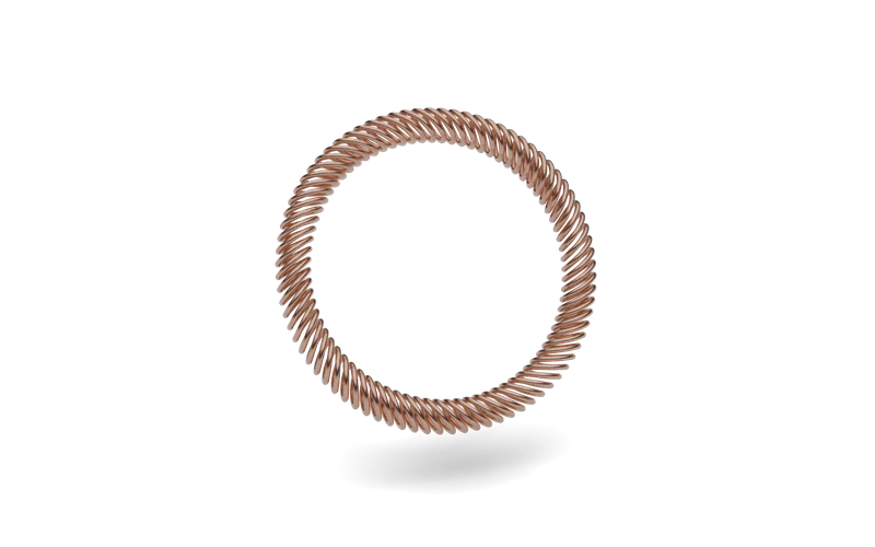
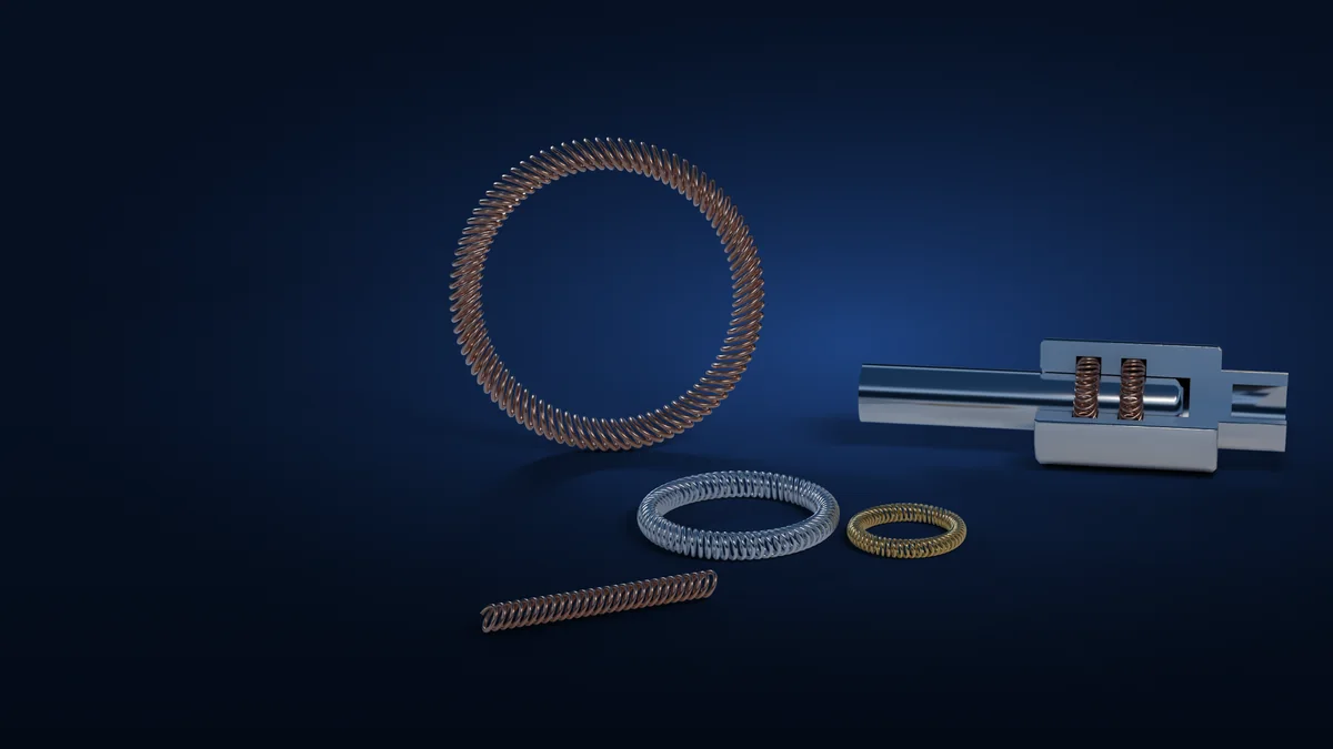
Schematic illustration of a canted coil spring formed into a ring
Schematic — canted coil spring ring
The Technology

What Is Canted Spring Contact Technology?

Canted spring contact elements are precision-engineered spring components designed to maintain controlled mechanical contact while supporting electrical current transfer in compact interfaces.

Unlike conventional compression springs, the geometry of a canted coil allows the spring to generate a controlled force characteristic as it is compressed laterally or within a dedicated groove or housing.

This makes the technology useful where electrical continuity, mechanical contact force, compact packaging and tolerance compensation need to work together.

Three-in-One

Three Functions. One Compact Contact Element.

01

Electrical Contact

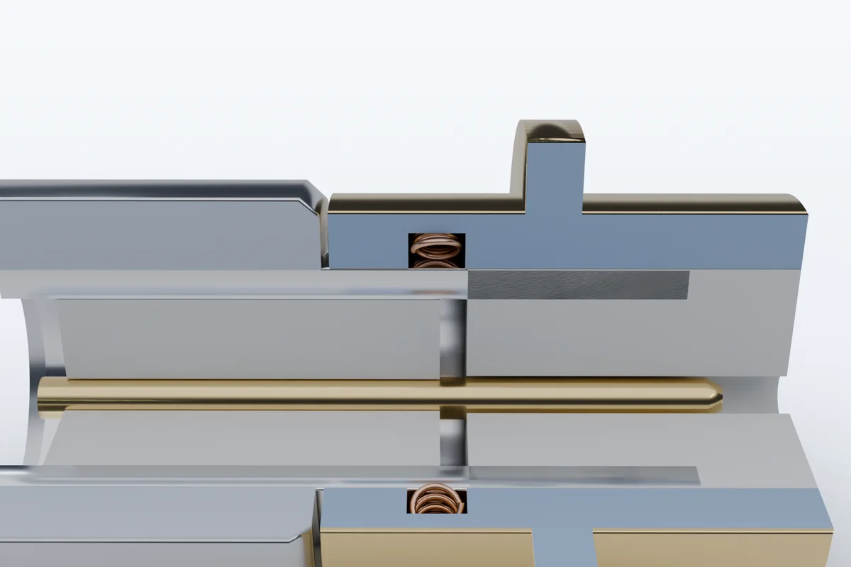
Many coil turns touch the mating surfaces at once, creating multiple contact points around the interface to support current transfer in compact connector designs.

Potential applications
  • High-current connectors
  • Power terminals
  • Switchgear interfaces
  • Cable connectors
  • High-voltage / medium-voltage equipment

Current-carrying capability depends on spring geometry, material, contact configuration, temperature and the specific application.
02

Mechanical Retention

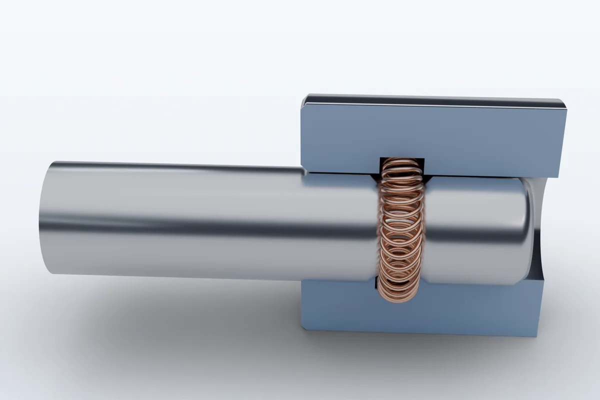
Within a designed groove or housing, the spring can provide controlled contact force and hold mating parts together without additional retaining hardware in selected designs.

Typical requirements
  • Controlled mating force
  • Controlled disengagement force
  • Mechanical retention
  • Compensation for dimensional variation
  • Static and dynamic applications

Force behaviour is designed around the mating geometry and the intended compression range.

03

EMI / RF Shielding

A continuous ring of conductive contact around a joint can help establish electrical continuity between housings and support an overall electromagnetic shielding strategy.

Potential applications
  • Electronic housings
  • Connector interfaces
  • Shielded enclosures
  • Rotating / sliding interfaces
  • Power electronics

Shielding effectiveness depends on the complete enclosure design and should be confirmed by testing.

Technology Principle

Controlled Force Across Real-World Variation

Canted spring geometry can be engineered to maintain useful contact force across a defined compression range, helping the interface accommodate dimensional variation and movement.

  1. 01Mating surface
  2. 02Canted spring
  3. 03Compression
  4. 04Contact force
  5. 05Stable interface
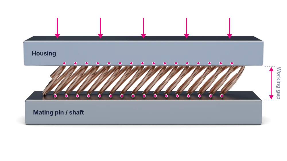
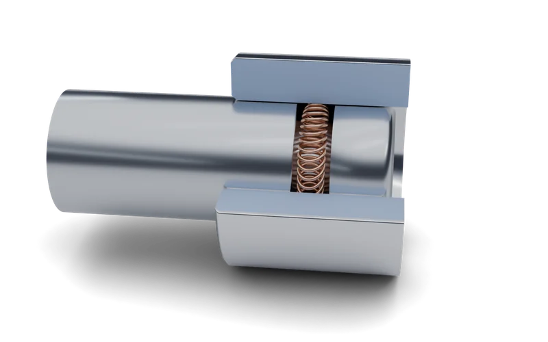
Canted spring contact principleInclined coil turns sit between a housing and a mating pin. When the pin is inserted the turns deflect together, each turn touching both surfaces and sharing the contact force.HousingMating pin / shaftEach inclined turn touches both surfaces and shares the loadWorking gap
Simplified cross-section. Inclined coil turns deflect together as the pin enters the housing; each turn contacts both surfaces.

What the spring helps accommodate

  • Dimensional tolerance between housing and mating part
  • Surface variation and finish differences
  • Thermal expansion and contraction in service
  • Moderate misalignment during assembly
  • Force stabilisation across the working compression range

The usable compression range and force level are set by the spring design and the groove it sits in, so both are specified together.

Key Benefits

Why Engineers Choose Spring Contact Elements

Multi-point contact

Contact is shared across many coil turns rather than relying on a single point or line.

Controlled spring force

Coil geometry can be selected to keep contact force within a useful band as the spring is compressed.

Tolerance compensation

Spring compliance can help accommodate defined dimensional variation and small movements.

Compact packaging

A single slim element can fit into tight connector envelopes and grooves.

Multi-function design

One element can potentially combine electrical contact with retention or shielding.

Application-specific configuration

Spring dimensions, material and finish are chosen around the actual interface.

Applications

Where Canted Spring Contact Technology Fits

Typical application areas are listed below. Not every spring configuration suits every application; suitability is confirmed for each interface during engineering review.

Power Transmission & Distribution

Canted spring contact technology can support compact electrical interfaces in power transmission and distribution equipment where controlled contact force, conductivity and tolerance compensation are important — for example GIS and AIS, circuit breakers, disconnects, current transformers, switchgear, ring main units and dead-tank equipment.

View industry

Switchgear & Circuit Breakers

Compact spring contact elements can be considered where controlled contact pressure, repeatable engagement over many operations and mechanical tolerance compensation are required, and may reduce component count in selected designs.

HV / MV Connectors

Canted spring contacts can provide multi-point conductive interfaces inside high- and medium-voltage connector architectures. Current transfer, contact resistance, thermal conditions, movement, connector envelope and insulation clearances are engineered together for each design.

Cable Terminations & Power Connectors

Spring contact technology can help maintain conductive interfaces in compact cable and connector assemblies where dimensional variation, assembly force and current transfer must be considered together.

Rotating / Moving Interfaces

Where electrical continuity must be kept while parts move relative to one another, an engineered spring contact can provide a compliant contact interface. Suitability depends on speed, travel and duty cycle.

Battery & Power Electronics

Potential applications include battery connectors, busbar interfaces, power modules and removable or serviceable power assemblies.

EMI / RF Shielding

Potential applications include equipment housings, electronics enclosures, connector interfaces, shield continuity across joints and RF-sensitive systems.

Industrial & Automotive Connectors

Potential applications include compact industrial power connectors and vehicle electrical interfaces where repeated mating, vibration and space constraints have to be balanced.

Materials

Materials & Surface Options

Material and surface finish are selected for conductivity, spring properties, temperature and corrosion exposure. Availability depends on configuration and application.

Potential material families

  • Copper alloys
  • Zirconium copper
  • Stainless steel
  • Other application-specific conductive or spring materials

Potential surface treatments

  • Silver
  • Gold
  • Tin
  • Nickel
  • Other application-specific coatings

Certification and compliance depend on the selected product configuration and manufacturer documentation.

Product Configurations

Formats Built Around the Interface

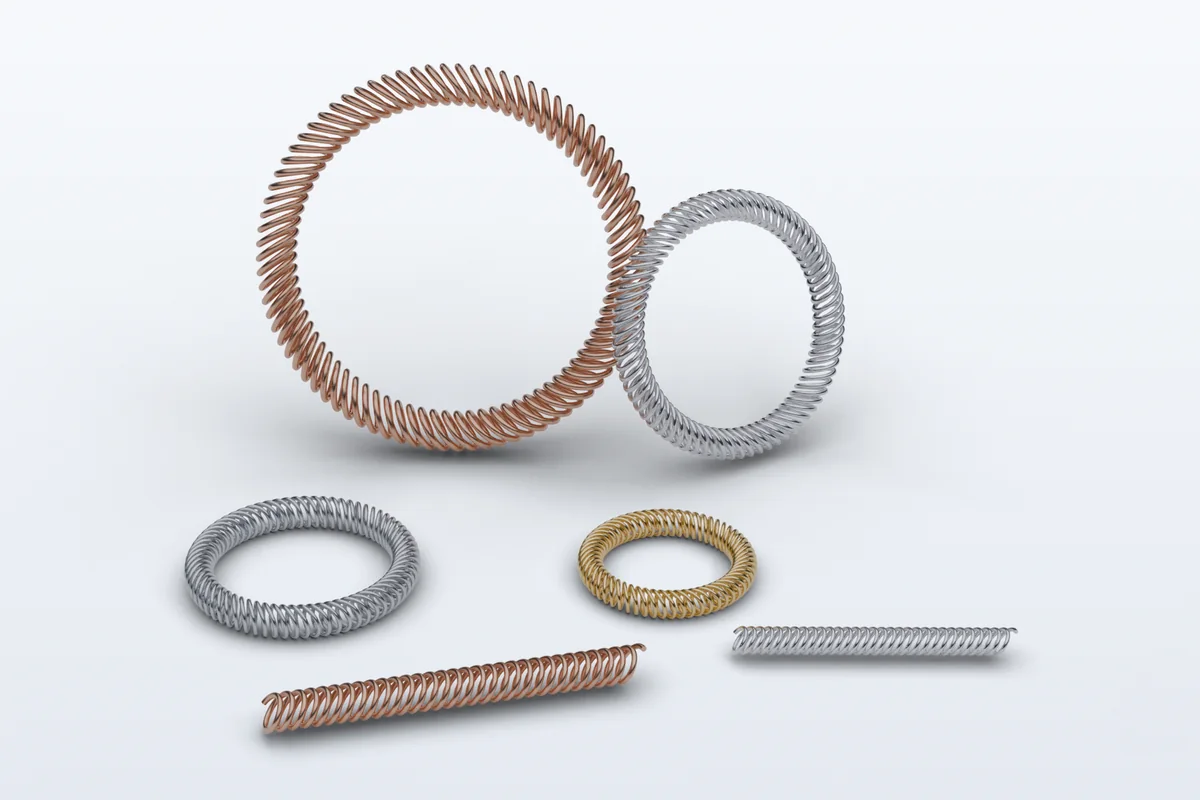
Canted spring contacts may be supplied or configured as spring rings, straight lengths, housing-mounted or piston-mounted arrangements, or dedicated connector geometries.

Spring rings

The coil is closed into a ring sized to a bore, pin or shaft diameter.

Straight lengths

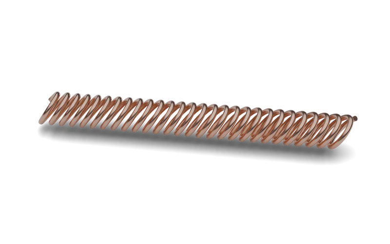
Continuous lengths for linear joints or for forming around custom contours.

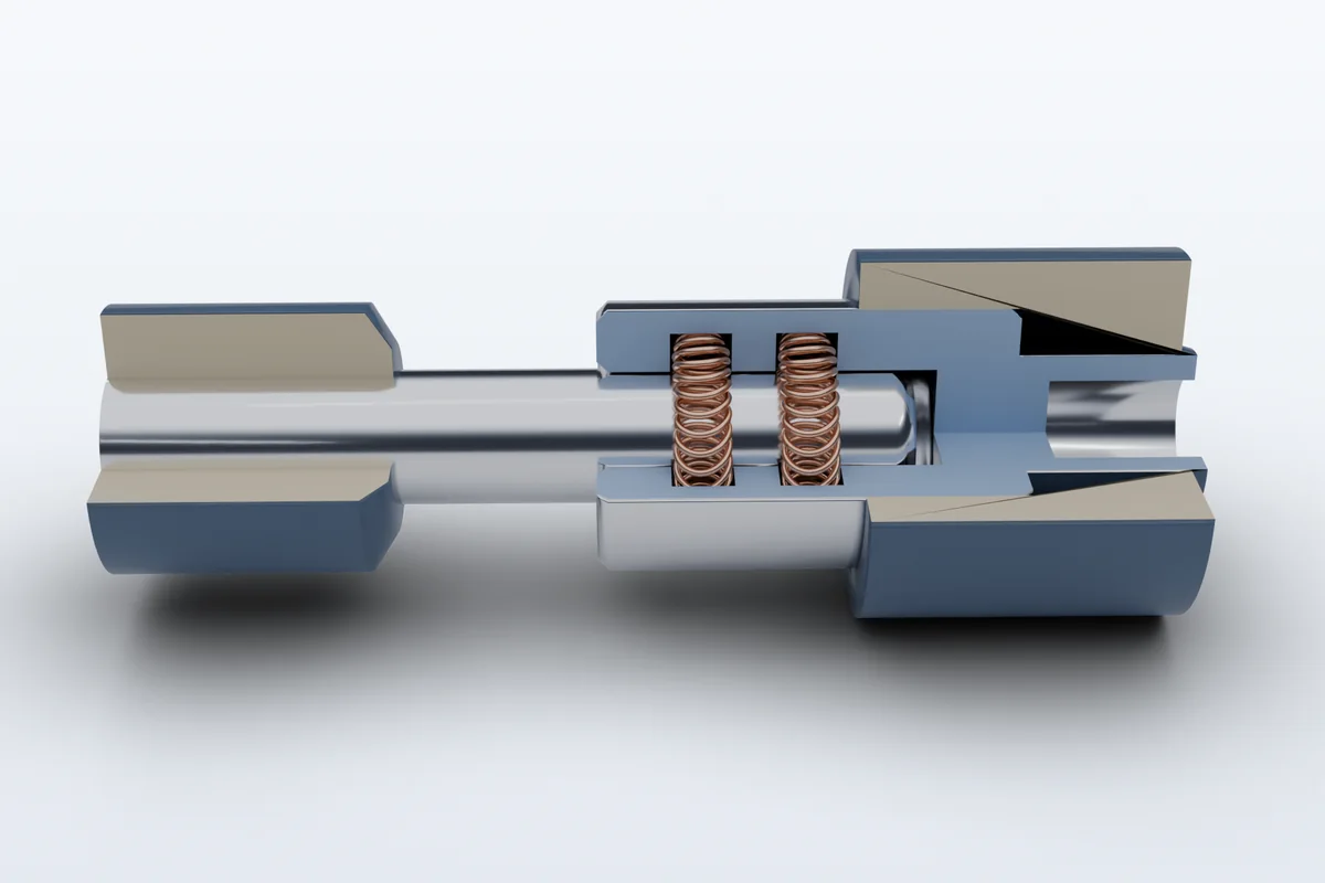
Housing-mounted

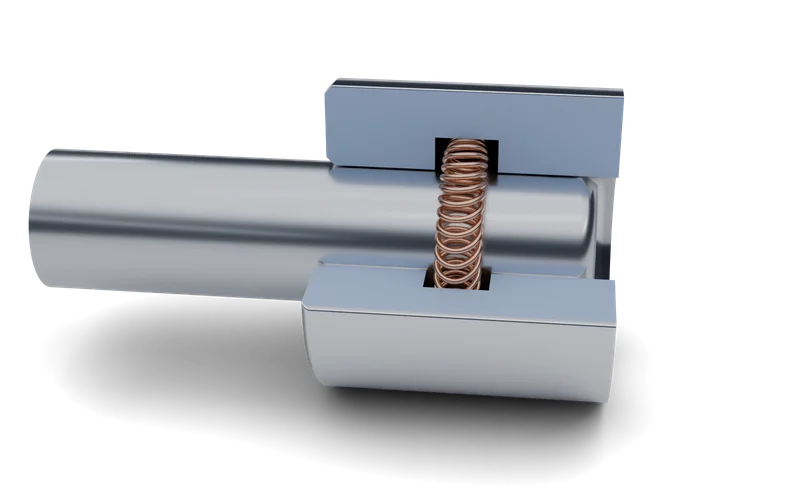
The spring sits in a groove in the outer housing and contacts the inserted pin.

Piston-mounted

The spring sits in a groove on the pin or shaft and contacts the surrounding bore.

Engineering Selection

The Right Contact Starts With the Interface

Selection begins with the requirements of the joint, not with a catalogue part. These six factors frame every enquiry.

01

Electrical Requirement

  • Continuous current
  • Short-circuit exposure
  • Contact resistance target
02

Mechanical Requirement

  • Insertion force
  • Removal force
  • Retention force
  • Dynamic movement
03

Geometry

  • Inner diameter
  • Spring width
  • Wire diameter
  • Groove / gland geometry
04

Environment

  • Temperature
  • Humidity
  • Corrosion exposure
  • Vibration
05

Material / Surface

  • Copper alloys
  • Stainless steel
  • Selected plating / coatings
06

Application Life

  • Mating cycles
  • Static / dynamic service
  • Maintenance requirements
Custom Engineering

Application-Specific Spring Contact Design

Canted spring contact performance depends strongly on the interface geometry and operating environment.

Haflinger can support customers in defining the application requirements used for spring/contact selection or custom development, and in coordinating that work with the manufacturer.

Engineering inputs may include
  • Contact diameter
  • Available groove / gland space
  • Wire diameter
  • Spring width
  • Compression range
  • Insertion / removal force
  • Current requirement
  • Short-circuit conditions
  • Temperature range
  • Operating environment
  • Mating cycles
  • Material requirements
  • Plating / coating requirements
How Haflinger Supports You

Application engineering

Defining the electrical, mechanical and environmental requirements of the interface.

Product selection

Shortlisting spring type, size, material and finish against those requirements.

Technical coordination

Coordinating drawings, samples and test planning between your team and the manufacturer.

Custom configuration

Supporting custom geometries where a standard spring does not fit the interface.

India-based support

Local engineering contact through enquiry, design review and supply.

Global coordination

Working with international engineering and manufacturing partners on your behalf.

Start an Engineering Enquiry

Have an interface that needs a better contact?

Share your application, dimensions and electrical requirements. Our engineers will review the interface and come back with suitable spring contact options.

Talk to Engineering Get a Quote